


FAAC Gate Opener Troubleshooting: E024S & E124 Board Guide
Start simple: tell us your control board and what the gate is doing, and get a short, safe next step. Deeper technical detail is one tap away when you need it.
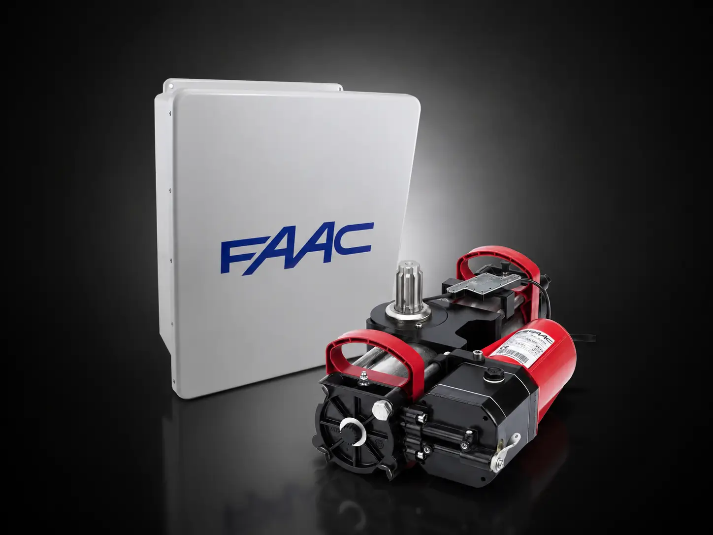
This is a two-path guide. The E024S reports faults with LEDs and is programmed with the SW1, SW2, and SW3 buttons. The E124 uses a digital display and the F, plus, and minus buttons, and shows numbered error codes. They are different boards with different steps, so follow only the path that matches yours. This page covers 24V FAAC swing-gate systems using one of these two boards.
Technically reviewed by [TECHNICIAN NAME], Automatic Gate Masters (CA Contractor #1060180). Published July 2026 · Last updated July 2026. Verified against the official FAAC E024S board manual (732642 Rev. D) and E124 board manual (532365 Rev. A), and UL 325. This guide is general information and not a substitute for a licensed on-site diagnosis.
Quick symptom chart
Find your symptom, see the most likely cause and one safe first check, then jump to the right board section. These are common causes, not confirmed diagnoses.
| Symptom | Most likely cause | Safe first check | Go to |
|---|---|---|---|
| Completely dead, no lights | No power, tripped breaker, or blown fuse | Reset the breaker and confirm power reaches the gate | E024S / E124 |
| Powered but will not move | Board is asking for a SETUP, or a safety input is active | Read the board indicators before doing anything | Setup |
| Opens but will not close | A closing safety input is active (often a photocell) | Clean and realign the closing photocells | Safety |
| Reverses or stops partway | An obstacle or the anti-crush tripped | Clear the path and check for a dragging leaf | Symptoms |
| Remote stopped working | Dead remote battery or a lost code | Replace the battery and test a second remote | E024S / E124 |
| E124 shows an error number | The code points to a specific fault | Look the number up in the E124 code tool | E124 codes |
MoreView all gate symptoms and board indicators
| Symptom | Most likely causes | Inspect first | E024S indicator | E124 indicator |
|---|---|---|---|---|
| Gate is completely dead | No power, tripped breaker, or a blown fuse | The breaker, incoming power, and the line fuse | No LEDs lit | Blank display |
| Board powered but gate does not move | Board requesting SETUP, a safety input active, or release disengaged | The board indicators before anything else | LD4 and LD5 flashing, or BUS LED slow-flashing | S0 flashing, or an Er code when you press + and - |
| Motor runs but gate does not move | Manual release disengaged, worn coupling, hydraulic by-pass or oil | That the release is engaged and locked | Motor powered, nothing moves | Possible motion timeout Er 32 |
| Only one leaf moves | One motor, encoder, or limit switch faulty, or leaf delay set wrong | The wiring and free movement of the stuck leaf | No leaf-specific code | Er 07/08 (motor), Er 06/16 (encoder), or Er 48/49 (limit switch) |
| Gate opens but will not close | A closing safety input active or a closing photocell blocked | The closing photocells and anything crossing the beam | BUS LED slow-flash while input engaged | IN5 active, or fail-safe Er 20 |
| Gate closes then immediately reopens | A closing photocell tripping, or an obstacle at the threshold | The closing beam and the sill area | BUS LED slow-flash as it reopens | IN5 active or obstacle Er 62/61 |
| Gate reverses while opening | Obstacle, opening safety, or force too low | The opening path and opening photocells | No dedicated LED; senses resistance | Er 31 (consecutive opening obstacle) or Er 61/62 |
| Gate reverses while closing | Obstacle, closing safety, or force too low | The closing path and closing photocells | No dedicated LED; senses resistance | Er 24 (consecutive closing obstacle) or Er 61/62 |
| Gate stops at the same spot every time | A limit switch, encoder, or mechanical obstruction at that point | That point in the travel for a bind or worn part | No dedicated LED | Er 32 timeout, or Er 48/49 limit switch |
| Gate moves slowly | Speed set low, low battery operation, or a binding gate | The battery status and free manual movement | LD8 shows the selected speed | Battery notification, or slowed speed setting |
| Gate is slow or sticky in cold weather | Thicker hydraulic oil or stiff mechanics in the cold | Nothing to adjust; usually normal in a cold snap | No code | No code |
| Gate stopped after a power outage | Tripped breaker, dead backup battery, or SETUP needed | The breaker and the backup battery | LD4/LD5 may flash for SETUP | S0 for SETUP, or battery notification |
| Gate works only while a button is held | Logic set to dead-man, or a safety fault forcing hold-to-run | The operating logic and the safety devices | Logic C (dead man) shown on LD7 | Logic set to hold-to-run, or a safety fault |
| Keypad works but the remote does not | Remote battery, unstored code, or receiver module | The remote battery, then re-store the remote | Re-store with SW3/SW2 + SW1 | Re-store with +/R1 or -/R2 |
| Remote works only from very close range | Weak remote battery or antenna problem | The remote battery and the antenna connection | Reseat the XF module | Reseat the XF module or antenna |
| Manual release will not re-engage | Gate not centered, tension on the operator, or a worn release | Gate position; move it slightly by hand and retry the key | No code | No code |
| Hydraulic operator is leaking oil | A seal or fitting issue on a hydraulic operator | Nothing DIY; note where it leaks | No code | No code |
| Gate binds when moved by hand | A mechanical problem: hinge, roller, track, or post shift | Hinges, rollers, and the swing path with power off | No code (mechanical) | No code (mechanical) |
| Board displays an error number | The E124 has detected a specific fault | The number, then the E124 error table | Not applicable; the E024S uses LEDs | Look up the Er code in the table below |
| SETUP will not complete | Motors reversed, a safety input active, or a mechanical stop not reached | That the leaves reach their stops and no input is active | LD4/LD5 keep flashing; leaves closing instead of opening means motor wires reversed | SETUP exits and S0 flashes; check errors with + and - |
Identify your control board
Open the operator cover or control box and find the circuit board. Pick the one that matches, or choose "I do not recognize my board".

FAAC E024S
24V swing · LEDsReports faults with LEDs, no screen. Programmed with three buttons.
RefE024S component reference
- SW1 SETUP starts the travel-learning cycle and restores defaults.
- SW2 SPEED sets speed and enters advanced programming.
- SW3 LOGIC selects the operating logic (A, E, and others).
- LD4 and LD5 are the SETUP LEDs. Both flashing means a SETUP is needed.
- BUS LED shows the safety-line status (see the pattern table).
- DS1 dip-switches set the motor type and force.
- F1 is the self-resetting accessory protection.
- F2 is the line and motor fuse.
- J9 / XF is the plug-in radio receiver module.
- BUS terminal (J10) connects BUS photocells and accessories.
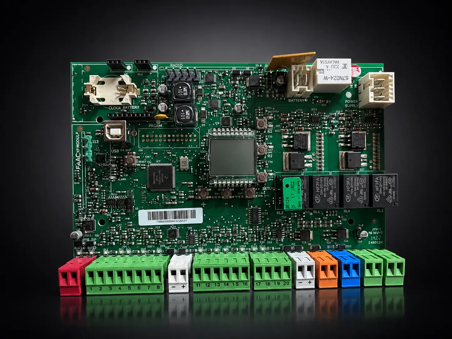
FAAC E124
24V swing · displayHas a two-digit display and shows numbered error codes. Programmed with F, plus, and minus.
RefE124 component reference
- Digital display shows the gate status and error codes.
- F button enters programming and confirms a value.
- Plus and minus buttons scroll and adjust, and jog the leaves during setup.
- R1 and R2 store remotes on OPEN A and OPEN B.
- 2EASY LEDs (DL12, DL13) show the BUS-2easy device status.
- XF / RADIO connector takes the plug-in radio receiver.
- MOT1 and MOT2 are the leaf 1 and leaf 2 motor terminals.
- Safety inputs (IN4, IN5) take the opening and closing safety devices.
- +24 accessory output powers photocells and accessories.
- F1 is the mains power-supply fuse (T 2.5 A).
If your board does not match either one above, it may be a different FAAC controller (or another brand), and these steps will not apply. Take a clear, well-lit photo of the whole board and text it to (650) 560-4646. We will tell you what you have and the right next step.
FAAC E024S troubleshooting
The E024S talks to you through its LEDs. Start with these safe checks, then open the advanced panels for board reading, setup, and remotes.
Basic checks (safe for anyone)
- No LEDs at all? Reset the breaker or GFCI and confirm power reaches the operator.
- LD4 and LD5 flashing slowly? The board is asking for a SETUP. Do not force it. See setup below.
- Gate opens but will not close? Clean and realign the photocells and clear the beam. A slow-flashing BUS LED means an input is engaged.
- Remote dead? Replace its battery and test a second remote before touching the board.
AdvancedRead the E024S LEDs and BUS LED
These meanings are E024S BUS LED behavior only. Do not apply them to a different board.
| BUS LED pattern | What it means (E024S) | What to do |
|---|---|---|
| Steady on | Normal. The BUS line is healthy, even with no photocells fitted | No action |
| Flashing about every 0.5s | At least one input is engaged | Find the active input (see note below) |
| Mostly off, brief flash about every 2.5s | The BUS line is short circuited | Check the BUS wiring |
| Rapid flash about every 0.2s | A BUS wiring error, or two devices share an address | Re-address or rewire the BUS devices |
A slow-flashing BUS LED means an input is active. That can be a blocked or misaligned photocell, but it can also be the OPEN A input, the OPEN B input, the STOP input, an access-control relay held closed, or a timer or hold-open command. Check what is actually holding the input before assuming a photocell.
Setup LEDs: LD4 and LD5 flashing slowly means a SETUP is required. During a SETUP both are lit steadily; they turn off when it succeeds, or keep flashing if it fails.
AdvancedDS1 motor selection and fuses (F1, F2)
The DS1 dip-switches must match your operator model, and they set the force. If the motor type is changed on DS1, the board requires a new SETUP. Setting the wrong motor type can damage the operator, so this is a technician adjustment.
F1 (accessory protection) is self-resetting. If an accessory such as a photocell or keypad draws too much current (over about 500mA) or shorts, F1 cuts the accessory power and resets itself after a few seconds. Repeated drop-outs point to a shorted accessory wire.
F2 (line and motor fuse) is a replaceable fuse rated T2A at 250V or T4A at 120V, depending on the board version. A blown F2 leaves the board dark. Replace it only with the exact rating, and if it blows again, stop and have the fault found.
AdvancedE024S remote programming
The E024S stores remotes on two channels: OPEN A (full open) with SW3, and OPEN B (partial open) with SW2. Only one radio family can be used at a time. Pick your remote type:
SLH remotes
On the remote, press and hold P1 and P2 until its LED flashes, then release. Within 5 seconds, hold the chosen remote button. On the board, press and hold SW3 (OPEN A) or SW2 (OPEN B) and, while holding it, press SW1. The board LED lights steady for a second to confirm. To add more remotes, transfer the code from a stored remote.
LC or RC remotes
On the board, press and hold SW3 (OPEN A) or SW2 (OPEN B) and, while holding it, press SW1. The channel LED flashes for 5 seconds. Within that window, press the remote button. The LED confirms with a steady second, then flashes again so you can add another remote.
DS remotes
Set the 12 dip-switches on the remote first. On the board, press and hold SW3 (OPEN A) or SW2 (OPEN B) and, while holding it, press SW1. The LED flashes for 5 seconds; within that window press the remote button. A maximum of two DS codes can be stored, one per channel.
To erase all stored remotes on the E024S, press and hold SW3 or SW2 together with SW1 for about 10 seconds. This cannot be undone, and every remote will need to be programmed again.
AdvancedRun an E024S SETUP (the gate moves)
A SETUP drives the gate through its full travel. Keep everyone out of the gate's path. If the leaves close instead of opening when the SETUP starts, the motor wires are reversed, which is a technician correction.
Confirm the DS1 motor setting
Make sure the DS1 dip-switches match your operator before starting.
Start the SETUP
Press and hold SW1 SETUP until LD4 and LD5 stay lit, then release. The leaves cycle open and closed one at a time to learn the limits.
Confirm success
When LD4 and LD5 turn off, the SETUP is done. If they keep flashing, repeat it. Finish by testing the photocells and the safety reverse.
Restore E024S factory defaults (last resort)
A factory restore erases the logic, pause time, force, and other settings, and deletes the SETUP. Use it only when needed. With the board off, hold SW1 SETUP while you switch the power on. Both SETUP LEDs light alternately while it clears, then LD4 and LD5 flash and you run a fresh SETUP.
FAAC E124 troubleshooting and error codes
The E124 shows a numbered code on its display. Start with the safe checks, then use the code tool to look up exactly what your gate is reporting.
Basic checks (safe for anyone)
- Blank display? Reset the breaker or GFCI and confirm power reaches the operator.
- Display flashing S0? The board needs a SETUP. Do not force it. See setup below.
- An error number showing? Press the plus and minus buttons together to read the active code, then look it up here.
- Remote dead? Replace its battery and test a second remote first.
Full listView all E124 error codes
| Code | Meaning | Likely cause | Safe first check | Power off first |
|---|---|---|---|---|
| Er 01 | Board failure | Internal control-board fault | Do a normal RESET (recessed RESET button) and watch the display. | No |
| Er 02 | Board thermal protection | The board is overheating from heavy or continuous use | Let the operator rest and cool down, then retry. Check the gate is not binding. | No |
| Er 06 | Encoder 2 fault | Leaf 2 encoder disconnected or faulty | Look for an obvious loose or damaged encoder cable. | Yes |
| Er 07 | Motor 1 fault | Leaf 1 motor disconnected or short circuited | Look for an obvious loose or damaged motor cable. | Yes |
| Er 08 | Motor 2 fault | Leaf 2 motor disconnected or short circuited | Look for an obvious loose or damaged motor cable. | Yes |
| Er 16 | Encoder 1 fault | Leaf 1 encoder disconnected or faulty | Look for an obvious loose or damaged encoder cable. | Yes |
| Er 20 | Fail-safe test failed | A safety device did not pass its self-test before moving | Check the photocells and safety edges are clean, aligned, and connected. | No |
| Er 22 | Programming data corrupted | Stored settings are invalid or corrupted | None. Note your settings if you can see them. | No |
| Er 24 | Consecutive obstacles while closing | The gate hit the set number of obstacles closing | Clear anything in the closing path and check for a dragging leaf. | No |
| Er 25 | Electric lock (LOCK1) fault | Electric lock wiring problem or short | Check for an obvious damaged lock cable. | Yes |
| Er 30 | Flashing light short circuit or overload | The flashing-lamp output is shorted or overloaded | Check the flashing-light wiring for a pinch or short. | Yes |
| Er 31 | Consecutive obstacles while opening | The gate hit the set number of obstacles opening | Clear anything in the opening path and check the leaf swings freely. | No |
| Er 32 | Motion timeout | A movement took longer than allowed | Confirm the manual release is engaged and the gate is not jammed. | No |
| Er 35 | BUS-2easy device fault or address conflict | Two BUS accessories share an address, or one is faulty | None. This is a wiring or addressing issue. | Yes |
| Er 36 | BUS-2easy short circuit or overload | The BUS-2easy line is shorted or overloaded | Look for an obviously pinched or damaged BUS cable. | Yes |
| Er 38 | Programming does not match SETUP | Settings changed after SETUP (for example two leaves enabled after a single-leaf SETUP) | None. | No |
| Er 39 | SETUP missing or incorrect | The board has not learned the travel | Confirm the gate moves freely by hand with power off, then a SETUP is needed. | Yes to check by hand |
| Er 48 | Limit-switch fault, leaf 1 | Leaf 1 limit switch wiring or position problem | Check for an obvious loose limit-switch wire. | Yes |
| Er 49 | Limit-switch fault, leaf 2 | Leaf 2 limit switch wiring or position problem | Check for an obvious loose limit-switch wire. | Yes |
| Er 61 | Obstacle detected, leaf 1 | Something is blocking leaf 1 | Clear the leaf 1 path and check the hinge and swing. | No |
| Er 62 | Obstacle detected, leaf 2 | Something is blocking leaf 2 | Clear the leaf 2 path and check the hinge and swing. | No |
| Er 70 | Emergency battery discharged | The backup battery is too low to move the gate | Restore mains power and let the battery recharge. | No |
| Er 76 | Radio code memory full | The remote memory is full | None. | No |
From the FAAC E124 manual (532365 Rev. A). Numbers 05, 09, 10, 11, 12, 13 are automation status codes, not errors.
AdvancedE124 buttons, display, and BUS status
The F button enters programming and confirms. The plus and minus buttons scroll and change values, and jog the leaves during setup. The two-digit display normally shows the gate status (for example 00 closed, 01 open, 05 opening, 06 closing). To read active notifications, press plus and minus together.
BUS-2easy status is shown by the on-board 2EASY LEDs and in the display. A device fault or address conflict shows as Er 35, and a short or overload as Er 36.
AdvancedE124 remote programming
The E124 stores remotes with the on-board radio buttons: plus / R1 for OPEN A (full open) and minus / R2 for OPEN B (partial open). It supports FAAC SLH, LC or RC, and DS remotes through the plug-in XF module.
SLH remotes
Press and hold the board plus/R1 (OPEN A) or minus/R2 (OPEN B) until the R1 or R2 LED flashes. On the remote, press P1 and P2 together until its LED flashes, then hold the chosen button near the board until the board LED goes steady for a second. Store, then press the remote twice to use it.
LC or RC remotes
Press and hold plus/R1 (OPEN A) or minus/R2 (OPEN B) until the R1 or R2 LED flashes. Press and release the remote button; the LED confirms with a steady moment, then flashes again so you can add another remote within about 20 seconds.
DS remotes
Set the remote dip-switches. Press and hold plus/R1 (OPEN A) or minus/R2 (OPEN B) until the LED flashes, then press and release the remote button within about 20 seconds to store it.
To erase all stored E124 remotes, press and hold the minus / R2 button. After about 5 seconds R2 flashes, then both R1 and R2 flash quickly while deleting, then light steadily when done. This cannot be undone.
AdvancedRun an E124 SETUP (the gate moves)
During an E124 SETUP the board moves the gate and temporarily disables the safety inputs while it learns the travel. Keep everyone completely clear of the gate.
Confirm the configuration
In Basic programming, confirm the automation type, number of motors, and encoder settings match your gate. The leaves must be closed.
Enter the tL function
Go to the tL function in Basic programming. The display shows two dashes.
Start and let it run
Press plus and minus together for a few seconds until the SETUP starts and the display shows S1. Let it run through its phases.
Confirm success
When the display shows 00, the SETUP is complete. If it stops early and S0 flashes, read the error code with plus and minus.
Restore E124 factory defaults (last resort)
A factory restore deletes the SETUP, all stored remotes, and the cycle counter, and returns every setting to default. Use it only when needed. With the board off, switch the power on and, while the display shows the firmware version, hold F, plus, and minus together for about 10 seconds until the display shows two dashes. Release, and the board then asks for a fresh SETUP (S0).
Setup, reset, and safety
A factory reset is rarely the first fix. Work through the checks in order, and know which jobs are safe and which need a technician.
Troubleshooting order for a gate that will not move
Identify the board and read it
E024S LEDs or E124 display. Confirm the board is actually asking for a SETUP before changing anything.
Photograph the current settings
Note or photograph existing settings so nothing is lost.
Check the manual release and free movement
Confirm the release is engaged, then, with power disconnected, confirm the gate moves freely by hand.
Run a normal SETUP, then restore defaults only if needed
Use the board-specific SETUP in the E024S or E124 section. A factory restore is a last resort because it erases installation settings.
Restoring defaults deletes the SETUP, the stored remotes, and installation-specific settings such as the operating logic, pause time, leaf delay, force, soft-stop, and accessory configuration. The exact restore steps are inside each board section above. Do not reset as a first move.
Which jobs are safe, and which need a pro
Level 1
Safe visual check, anyone
- Clean photocell lenses
- Replace a remote battery
- Remove debris from the path
- Check whether the breaker tripped
- Observe the LEDs or display
- Test a second remote
Level 2
Disconnect power first
- Inspect low-voltage wiring
- Reseat a receiver module
- Check a fuse condition
- Check for loose terminals
- Move the gate manually
Level 3
Licensed technician only
- Mains 115V or 230V diagnosis
- Replacing a control board
- Motor wiring or replacement
- Force or by-pass adjustment
- Hydraulic service
- Encoder or limit tuning
- UL 325 entrapment testing
Do not disable or bypass photocells, safety edges, loops, or monitored inputs to make the gate move. If the gate will not reverse properly, or moves with a failed safety device, stop using it and call a qualified gate technician. Automatic gate operators must meet UL 325 for reversing and entrapment protection.
FAAC troubleshooting FAQ
Does this guide cover my FAAC control board?
What is the difference between the E024S and E124 boards?
My FAAC gate opens but will not close, what is the most likely cause?
What does an error number on my E124 display mean?
How do I reprogram a remote on my FAAC gate?
Should I do a factory reset if my gate will not move?
Is it safe to swap the motor wires or work on the board myself?
Why does a SETUP make the gate move on its own?
What do the flashing SETUP LEDs on my E024S mean?
Sources: FAAC E024S control board manual, document 732642 Rev. D (FAAC S.p.A.) · FAAC E124 control board manual, document 532365 Rev. A (FAAC S.p.A.) · UL 325, Standard for Safety for Door, Drapery, Gate, Louver, and Window Operators and Systems. Manufacturer documentation is available from FAAC. This guide is general information, not a substitute for a licensed on-site diagnosis.
Still stuck? Get a licensed FAAC technician
If the board, power, and photocells all check out and the gate still will not run right, we diagnose E024S and E124 systems on site across the Bay Area, with a free written estimate.